
SwiftGL
Hello Triangle
In OpenGL everything is in 3D space, but the screen and window are a 2D array of pixels so a large part of OpenGL’s work is about transforming all 3D coordinates to 2D pixels that fit on your screen. The process of transforming 3D coordinates to 2D coordinates is managed by the graphics pipeline of OpenGL. The graphics pipeline can be divided into two large parts: the first transforms your 3D coordinates into 2D coordinates and the second part transforms the 2D coordinates into actual colored pixels. In this tutorial we’ll briefly discuss the graphics pipeline and how we can use it to our advantage to create some fancy pixels.
There is a difference between a 2D coordinate and a pixel. A 2D coordinate is an infinitely precise representation of where a point is in 2D space. A a 2D pixel is tiny, but tangible, area which is capable of being displayed on your screen.
The graphics pipeline takes as input a set of 3D coordinates and transforms these to colored 2D pixels on your screen. The graphics pipeline can be divided into several steps where each step requires the output of the previous step as its input. All of these steps are highly specialized (they have one specific function) and can easily be executed in parallel. Because of their parallel nature most graphics cards of today have thousands of small processing cores to quickly process your data within the graphics pipeline by running small programs on the GPU for each step of the pipeline. These small programs are called shaders.
Some of these shaders are configurable by the developer which allows us to write our own shaders to replace the existing default shaders. This gives us much more fine-grained control over specific parts of the pipeline and because they run on the GPU, they can also save us valuable CPU time. Shaders are written in the OpenGL Shading Language (GLSL) and we’ll delve more into that in the next tutorial.
Below you’ll find an abstract representation of all the stages of the graphics pipeline. Note that the blue sections represent sections where we can inject our own shaders.
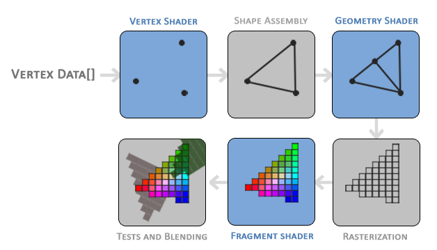
As you can see the graphics pipeline contains a large number of sections that each handle one specific part of converting your vertex data to a fully rendered pixel. We will briefly explain each part of the pipeline in a simplified way to give you a good overview of how the pipeline operates.
As input to the graphics pipeline we pass in a list of three 3D coordinates that should form a triangle in an array here called Vertex Data; this vertex data is a collection of vertices. A vertex is basically a collection of data per 3D coordinate. This vertex’s data is represented using vertex attributes that can contain any data we’d like but for simplicity’s sake let’s assume that each vertex consists of just a 3D position and some color value.
In order for OpenGL to know what to make of your collection of coordinates and color values OpenGL requires you to hint what kind of render types you want to form with the data. Do we want the data rendered as a collection of points, a collection of triangles or perhaps just one long line? Those hints are called primitives and are given to OpenGL while calling any of the drawing commands. Some of these hints are GL_POINTS, GL_TRIANGLES and GL_LINE_STRIP.
The first part of the pipeline is the vertex shader that takes as input a single vertex. The main purpose of the vertex shader is to transform 3D coordinates into different 3D coordinates (more on that later) and the vertex shader allows us to do some basic processing on the vertex attributes.
The primitive assembly stage takes as input all the vertices (or vertex if GL_POINTS is chosen) from the vertex shader that form a primitive and assembles all the point(s) in the primitive shape given; in this case a triangle.
The output of the primitive assembly stage is passed to the geometry shader. The geometry shader takes as input a collection of vertices that form a primitive and has the ability to generate other shapes by emitting new vertices to form new (or other) primitive(s). In this example case, it generates a second triangle out of the given shape.
The output of the geometry shader is then passed on to the rasterization stage where it maps the resulting primitive(s) to the corresponding pixels on the final screen, resulting in fragments for the fragment shader to use. Before the fragment shaders runs, clipping is performed. Clipping discards all fragments that are outside your view, increasing performance.
A fragment in OpenGL is all the data required for OpenGL to render a single pixel.
The main purpose of the fragment shader is to calculate the final color of a pixel and this is usually the stage where all the advanced OpenGL effects occur. Usually the fragment shader contains data about the 3D scene that it can use to calculate the final pixel color (like lights, shadows, color of the light and so on).
After all the corresponding color values have been determined, the final object will then pass through one more stage that we call the alpha test and blending stage. This stage checks the corresponding depth (and stencil) value (we’ll get to those later) of the fragment and uses those to check if the resulting fragment is in front or behind other objects and should be discarded accordingly. The stage also checks for alpha values (alpha values define the opacity of an object) and blends the objects accordingly. So even if a pixel output color is calculated in the fragment shader, the final pixel color could still be something entirely different when rendering multiple triangles.
As you can see, the graphics pipeline is quite a complex whole and contains many configurable parts. However, for almost all the cases we only have to work with the vertex and fragment shader. The geometry shader is optional and usually left to its default shader.
In Modern OpenGL we are required to define at least a vertex and fragment shader of our own (there are no default vertex/fragment shaders on the GPU). For this reason it is often quite difficult to start learning Modern OpenGL since a great deal of knowledge is required before being able to render your first triangle. Once you do get to finally render your triangle at the end of this chapter you will end up knowing a lot more about graphics programming.
Vertex input
To start drawing something we have to first give OpenGL some input vertex data. OpenGL is a 3D graphics library so all coordinates that we specify in OpenGL are in 3D (x, y and z coordinate). OpenGL doesn’t simply transform all your 3D coordinates to 2D pixels on your screen; OpenGL only processes 3D coordinates when they’re in a specific range between -1.0 and 1.0 on all 3 axes (x, y and z). All coordinates within this so called normalized device coordinates range will end up visible on your screen (and all coordinates outside this region won’t).
Because we want to render a single triangle we want to specify a total of three vertices with each vertex having a 3D position. We define them in normalized device coordinates (the visible region of OpenGL) in a GLfloat array:
let vertices:[GLfloat] = [
  -0.5, -0.5, 0.0,
   0.5, -0.5, 0.0,
   0.0,  0.5, 0.0
]
Because OpenGL works in 3D space we render a 2D triangle with each vertex having a z coordinate of 0.0. This way the depth of the triangle remains the same making it look like it’s 2D.
Normalized Device Coordinates (NDC)
Once your vertex coordinates have been processed in the vertex shader, they should be in normalized device coordinates which is a small space where the x, y and z values vary from -1.0 to 1.0. Any coordinates that fall outside this range will be discarded/clipped and won't be visible on your screen. Below you can see the triangle we specified within normalized device coordinates (ignoring the z axis):
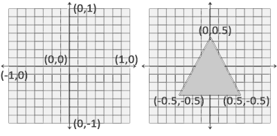
Unlike usual screen coordinates the positive y-axis points in the up-direction and the (0,0) coordinates are at the center of the graph, instead of top-left. Eventually you want all the (transformed) coordinates to end up in this coordinate space, otherwise they won't be visible.
Your NDC coordinates will then be transformed to screen-space coordinates via the viewport transform using the data you provided with glViewport. The resulting screen-space coordinates are then transformed to fragments as inputs to your fragment shader.
With the vertex data defined we’d like to send it as input to the first process of the graphics pipeline: the vertex shader. This is done by creating memory on the GPU where we store the vertex data, configure how OpenGL should interpret the memory and specify how to send the data to the graphics card. The vertex shader then processes as much vertices as we tell it to from its memory.
We manage this memory via so called vertex buffer objects (VBO) that can store a large number of vertices in the GPU’s memory. The advantage of using those buffer objects is that we can send large batches of data all at once to the graphics card without having to send data a vertex a time. Sending data to the graphics card from the CPU is relatively slow, so wherever we can we try to send as much data as possible at once. Once the data is in the graphics card’s memory the vertex shader has almost instant access to the vertices making it extremely fast
A vertex buffer object is our first occurrence of an OpenGL object as we’ve discussed in the OpenGL tutorial. Just like any object in OpenGL this buffer has a unique ID corresponding to that buffer, so we can generate one with a buffer ID using the glGenBuffers function:
var VBO:GLuint = 0
glGenBuffers(n: 1, buffers: &VBO)
defer { glDeleteBuffers(1, &VBO) }
OpenGL has many types of buffer objects and the buffer type of a vertex buffer object is GL_ARRAY_BUFFER. OpenGL allows us to bind to several buffers at once as long as they have a different buffer type. We can bind the newly created buffer to the GL_ARRAY_BUFFER target with the glBindBuffer function:
glBindBuffer(target: GL_ARRAY_BUFFER, buffer: VBO)From that point on any buffer calls we make (on the GL_ARRAY_BUFFER target) will be used to configure the currently bound buffer, which is VBO. Then we can make a call to glBufferData function that copies the previously defined vertex data into the buffer’s memory:
glBufferData(target: GL_ARRAY_BUFFER,
    size: strideof(GLfloat) * vertices.count,
    data: vertices, usage: GL_STATIC_DRAW)
glBufferData is a function specifically targeted to copy user-defined data into the currently bound buffer. Its first argument is the type of the buffer we want to copy data into: the vertex buffer object currently bound to the GL_ARRAY_BUFFER target. The second argument specifies the size of the data (in bytes) we want to pass to the buffer; a simple sizeof of the vertex data suffices. The third parameter is the actual data we want to send.
The fourth parameter specifies how we want the graphics card to manage the given data. This can take 3 forms:
GL_STATIC_DRAW: the data will most likely not change at all or very rarely.GL_DYNAMIC_DRAW: the data is likely to change a lot.GL_STREAM_DRAW: the data will change every time it is drawn.
The position data of our triangle does not change and stays the same for every render call so its usage type should best be GL_STATIC_DRAW. If, for instance, one would have a buffer with data that is likely to change frequently, a usage type of GL_DYNAMIC_DRAW or GL_STREAM_DRAW ensures the graphics card will place the data in memory that allows for faster writes.
As of now we stored the vertex data within memory on the graphics card as managed by a vertex buffer object named VBO. Next we want to create a vertex and fragment shader that actually processes this data, so let’s start building those.
Vertex shader
The vertex shader is one of the shaders that are programmable by people like us. Modern OpenGL requires that we at least set up a vertex and fragment shader if we want to do some rendering so we will briefly introduce shaders and configure two very simple shaders for drawing our first triangle. In the next tutorial we’ll discuss shaders in more detail.
The first thing we need to do is write the vertex shader in the shader language GLSL (OpenGL Shading Language) and then compile this shader so we can use it in our application. Below you’ll find the source code of a very basic vertex shader in GLSL:
#version 330 core

layout (location = 0) in vec3 position;

void main()
{
    gl_Position = vec4(position.x, position.y, position.z, 1.0);
}
As you can see, GLSL looks similar to C. Each shader begins with a declaration of its version. Since OpenGL 3.3 and higher the version numbers of GLSL match the version of OpenGL (GLSL version 420 corresponds to OpenGL version 4.2 for example). We also explicitly mention we’re using core profile functionality.
Next we declare all the input vertex attributes in the vertex shader with the in keyword. Right now we only care about position data so we only need a single vertex attribute. GLSL has a vector datatype that contains 1 to 4 floats based on its postfix digit. Since each vertex has a 3D coordinate we create a vec3 input variable with the name position. We also specifically set the location of the input variable via layout (location = 0) and you’ll later see that why we’re going to need that location.
Vector
In graphics programming we use the mathematical concept of a vector quite often, since it neatly represents positions/directions in any space and has useful mathematical properties. A vector in GLSL has a maximum size of 4 and each of its values can be retrieved via vec.x, vec.y, vec.z and vec.w respectively where each of them represents a coordinate in space. Note that the vec.w component is not used as a position in space (we’re dealing with 3D, not 4D) but is used for something called perspective division. We’ll discuss vectors in much greater depth in a later tutorial.
To set the output of the vertex shader we have to assign the position data to the predefined gl_Position variable which is a vec4 behind the scenes. At the end of the main function, whatever we set gl_Position to will be used as the output of the vertex shader. Since our input is a vector of size 3 we have to cast this to a vector of size 4. We can do this by inserting the vec3 values inside the constructor of vec4 and set its w component to 1.0f (we will explain why in a later tutorial).
The current vertex shader is probably the most simple vertex shader we can imagine because we did no processing whatsoever on the input data and simply forwarded it to the shader’s output. In real applications the input data is usually not already in normalized device coordinates so we first have to transform the input data to coordinates that fall within OpenGL’s visible region
Compiling a shader
We wrote the source code for the vertex shader (stored in a String), but in order for OpenGL to use the shader it has to dynamically compile it at run-time from its source code.
The first thing we need to do is create a shader object, again referenced by an ID. So we store the vertex shader as a GLuint and create the shader with glCreateShader:
let vertexShader:GLuint = glCreateShader(type: GL_VERTEX_SHADER)We provide the type of shader we want to create as an argument to glCreateShader. Since we’re creating a vertex shader we pass in GL_VERTEX_SHADER.
Next we attach the shader source code to the shader object and compile the shader:
vertexShaderSource.withCString {
    var s = [$0]
    glShaderSource(shader: vertexShader, count: 1, string: &s, length: nil)
}
glCompileShader(vertexShader)
The glShaderSource function takes the shader object to compile to as its first argument. The second argument specifies how many strings we’re passing as source code, which is only one. The third parameter is the actual source code of the vertex shader and we can leave the 4th parameter to NULL.
The withCString closure is used because glShaderSource expects an array of C strings. This is handy if you write a shader that spans multiple files. We have only one small string so we must construct the expected array.
You probably want to check if compilation was successful after the call to glCompileShader and if not, what errors were found so you can fix those. Checking for compile-time errors is accomplished as follows:
var success:GLint = 0
glGetShaderiv(vertexShader, GL_COMPILE_STATUS, &success)
First we define an integer to indicate success and a storage container for the error messages (if any). Then we check if compilation was successful with glGetShaderiv. If compilation failed, we should retrieve the error message with glGetShaderInfoLog and print the error message.
var infoLog = [GLchar](count: 512, repeatedValue: 0)
guard success == GL_TRUE else
{
    glGetShaderInfoLog(vertexShader, 512, nil, &infoLog)
    fatalError(String.fromCString(infoLog)!)
}
If no errors were detected while compiling the vertex shader it is now compiled.
Fragment shader
The fragment shader is the second and final shader we’re going to create for rendering a triangle. The fragment shader is all about calculating the color output of your pixels. To keep things simple the fragment shader will always output an orange-ish color.
Colors in computer graphics are represented as an array of 4 values: the red, green, blue and alpha (opacity) component, commonly abbreviated to RGBA. When defining a color in OpenGL or GLSL we set the strength of each component to a value between 0.0 and 1.0. If, for example, we would set red to 1.0 and green to 1.0 we would get a mixture of both colors and get the color yellow. Given those 3 color components we can generate every color in the rainbow.
#version 330 core

out vec4 color;

void main()
{
    color = vec4(1.0f, 0.5f, 0.2f, 1.0f);
}
The fragment shader only requires one output variable and that is a vector of size 4 that defines the final color output that we should calculate ourselves. We can declare output values with the out keyword, that we here promptly named color. Next we simply assign a vec4 to the color output as an orange color with an alpha value of 1.0 (1.0 being completely opaque).
The process for compiling a fragment shader is similar to the vertex shader, although this time we use the GL_FRAGMENT_SHADER constant as the shader type:
let fragmentShader:GLuint = glCreateShader(type: GL_FRAGMENT_SHADER)
fragmentShaderSource.withCString {
    var s = [$0]
    glShaderSource(shader: fragmentShader, count: 1, string: &s, length: nil)
}
glCompileShader(fragmentShader)
Both the shaders are now compiled and the only thing left to do is link both shader objects into a shader program that we can use for rendering.
Shader program
A shader program object is the final linked version of multiple shaders combined. To use the recently compiled shaders we have to link them to a shader program object and then activate this shader program when rendering objects. The activated shader program’s shaders will be used when we issue render calls.
When linking the shaders into a program it links the outputs of each shader to the inputs of the next shader. This is also where you’ll get linking errors if your outputs and inputs do not match.
Creating a program object is easy:
let shaderProgram:GLuint = glCreateProgram()The glCreateProgram function creates a program and returns the ID reference to the newly created program object. Now we need to attach the previously compiled shaders to the program object and then link them with glLinkProgram:
glAttachShader(shaderProgram, vertexShader)
glAttachShader(shaderProgram, fragmentShader)
glLinkProgram(shaderProgram)
The code should be pretty self-explanatory, we attach the shaders to the program and link them via glLinkProgram.
Just like shader compilation we can also check if linking a shader program failed and retrieve the corresponding log. However, instead of using glGetShaderiv and glGetShaderInfoLog we now use:
glGetProgramiv(shaderProgram, GL_LINK_STATUS, &success)
guard success == GL_TRUE else
{
    glGetProgramInfoLog(shaderProgram, 512, nil, &infoLog)
    fatalError(String.fromCString(infoLog)!)
}
If all is well, the result is a program object that we can activate by calling glUseProgram with the newly created program object as its argument:
glUseProgram(shaderProgram)Every shader and rendering call after glUseProgram will now use this program object (and thus the shaders).
Oh yeah, and don’t forget to delete the shader objects once we’ve linked them into the program object; we no longer need them anymore:
glDeleteShader(vertexShader)
glDeleteShader(fragmentShader)
Right now we sent the input vertex data to the GPU and instructed the GPU how it should process the vertex data within a vertex and fragment shader. We’re almost there, but not quite yet. OpenGL does not yet know how it should interpret the vertex data in memory and how it should connect the vertex data to the vertex shader’s attributes. We’ll be nice and tell OpenGL how to do that.
Linking vertex attributes
The vertex shader allows us to specify any input we want in the form of vertex attributes and while this allows for great flexibility, it does mean we have to manually specify what part of our input data goes to which vertex attribute in the vertex shader. This means we have to specify how OpenGL should interpret the vertex data before rendering.
Our vertex buffer data is formatted as follows:
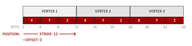
- The position data is stored as 32-bit (4 byte) floating point values.
- Each position is composed of 3 of those values.
- There is no space (or other values) between each set of 3 values. The values are tightly packed in the array.
- The first value in the data is at the beginning of the buffer.
With this knowledge we can tell OpenGL how it should interpret the vertex data (per vertex attribute) using glVertexAttribPointer:
glVertexAttribPointer(index: 0, size: 3, type: GL_FLOAT,
    normalized: false, stride: GLsizei(strideof(GLfloat) * 3), pointer: nil)
glEnableVertexAttribArray(0)
The function glVertexAttribPointer has quite a few parameters so let’s carefully walk through them:
- The first parameter specifies which vertex attribute we want to configure. Remember that we specified the location of the
positionvertex attribute in the vertex shader withlayout (location = 0). This sets the location of the vertex attribute to 0 and since we want to pass data to this vertex attribute, we pass in 0. - The next argument specifies the size of the vertex attribute. The vertex attribute is a
vec3so it is composed of 3 values. - The third argument specifies the type of the data which is
GL_FLOAT(avec*in GLSL consists of floating point values). - The next argument specifies if we want the data to be normalized. If we set this to
trueall the data that has a value not between 0 (or -1 for signed data) and 1 will be mapped to those values. We leave this atfalse. - The fifth argument is known as the stride and tells us the space between consecutive vertex attribute sets. Since the next set of position data is located exactly 3 times the size of a
GLfloataway we specify that value as the stride. Note that since we know that the array is tightly packed (there is no space between the next vertex attribute value) we could’ve also specified the stride as 0 to let OpenGL determine the stride (this only works when values are tightly packed). Whenever we have more vertex attributes we have to carefully define the spacing between each vertex attribute but we’ll get to see more examples of that later on. - The last parameter is of type
GLvoid*and thus requires that weird cast. This is the offset of where the position data begins in the buffer. Since the position data is at the start of the data array this value is just 0. We will explore this parameter in more detail later on
Each vertex attribute takes its data from memory managed by a VBO and which VBO it takes its data from (one could have multiple VBOs) is determined by the VBO currently bound to GL_ARRAY_BUFFER when calling glVertexAttribPointer. Since the previously defined VBO was bound before calling glVertexAttribPointer vertex attribute 0 is now associated with its vertex data.
Now that we specified how OpenGL should interpret the vertex data we should also enable the vertex attribute with glEnableVertexAttribArray giving the vertex attribute location as its argument; vertex attributes are disabled by default. From that point on we have everything set up: we initialized the vertex data in a buffer using a vertex buffer object, set up a vertex and fragment shader and told OpenGL how to link the vertex data to the vertex shader’s vertex attributes. Drawing an object in OpenGL would now look something like this:
// 0. Copy our vertices array in a buffer for OpenGL to use
glBindBuffer(target: GL_ARRAY_BUFFER, buffer: VBO)
glBufferData(target: GL_ARRAY_BUFFER,
    size: strideof(GLfloat) * vertices.count,
    data: vertices, usage: GL_STATIC_DRAW)
// 1. Then set the vertex attributes pointers
glVertexAttribPointer(index: 0, size: 3, type: GL_FLOAT,
    normalized: false, stride: GLsizei(strideof(GLfloat) * 3), pointer: nil)
glEnableVertexAttribArray(0)
// 2. Use our shader program when we want to render an object
glUseProgram(shaderProgram);
// 3. Now draw the object
someOpenGLFunctionThatDrawsOurTriangle();
We have to repeat this process every time we want to draw an object. It may not look like that much, but imagine if we have over 5 vertex attributes and perhaps 100s of different objects (which is not uncommon). Binding the appropriate buffer objects and configuring all vertex attributes for each of those objects quickly becomes a cumbersome process. What if there was some way we could store all these state configurations into an object and simply bind this object to restore its state?
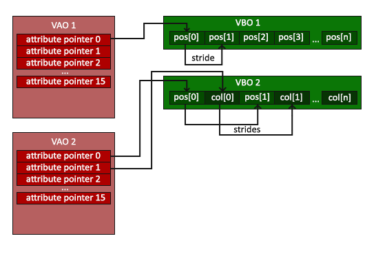
Vertex Array Object
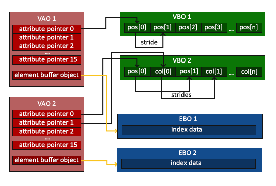
A vertex array object (also known as VAO) can be bound just like a vertex buffer object and any subsequent vertex attribute calls from that point on will be stored inside the VAO. This has the advantage that when configuring vertex attribute pointers you only have to make those calls once and whenever we want to draw the object, we can just bind the corresponding VAO. This makes switching between different vertex data and attribute configurations as easy as binding a different VAO. All the state we just set is stored inside the VAO.
Core OpenGL requires that we use a VAO so it knows what to do with our vertex inputs. If we fail to bind a VAO, OpenGL will most likely refuse to draw anything.
A vertex array object stores the following:
- Calls to
glEnableVertexAttribArrayorglDisableVertexAttribArray. - Vertex attribute configurations via
glVertexAttribPointer. - Vertex buffer objects associated with vertex attributes by calls to
glVertexAttribPointer.
The process to generate a VAO looks simliar to that of a VBO:
var VAO:GLuint = 0
glGenVertexArrays(n: 1, arrays: &VAO)
defer { glDeleteVertexArrays(1, &VAO) }
To use a VAO all you have to do is bind the VAO using glBindVertexArray. From that point on we should bind/configure the corresponding VBO(s) and attribute pointer(s) and then unbind the VAO for later use. As soon as we want to draw an object, we simply bind the VAO with the preferred settings before drawing the object and that is it. In code this would look a bit like this:
// ..:: Initialization code (done once (unless your object frequently changes)) :: ..
// 1. Bind Vertex Array Object
glBindVertexArray(VAO)
    // 2. Copy our vertices array in a buffer for OpenGL to use
    glBindBuffer(target: GL_ARRAY_BUFFER, buffer: VBO)
    glBufferData(target: GL_ARRAY_BUFFER,
        size: strideof(GLfloat) * vertices.count,
        data: vertices, usage: GL_STATIC_DRAW)
    // 3. Then set our vertex attributes pointers
    glVertexAttribPointer(index: 0, size: 3, type: GL_FLOAT,
        normalized: false, stride: GLsizei(strideof(GLfloat) * 3), pointer: nil)
    glEnableVertexAttribArray(0)
//4. Unbind the VAO
glBindVertexArray(0)

[...]

// ..:: Drawing code (in Game loop) :: ..
// 5. Draw the object
glUseProgram(shaderProgram)
glBindVertexArray(VAO)
someOpenGLFunctionThatDrawsOurTriangle()
glBindVertexArray(0)
It is common practice to unbind OpenGL objects when we’re done configuring them so we don’t mistakenly (mis)configure them elsewhere.
And that is it! Everything we did the last few million pages led up to this moment, a VAO that stores our vertex attribute configuration and which VBO to use. Usually when you have multiple objects you want to draw, you first generate/configure all the VAOs (and thus the required VBO and attribute pointers) and store those for later use. The moment we want to draw one of our objects, we take the corresponding VAO, bind it, then draw the object and unbind the VAO again.
The triangle we’ve been waiting for
To draw our objects of choice OpenGL provides us with the glDrawArrays function that draws primitives using the currently active shader, the previously defined vertex attribute configuration and with the VBO’s vertex data (indirectly bound via the VAO).
glUseProgram(shaderProgram)
glBindVertexArray(VAO)
glDrawArrays(GL_TRIANGLES, 0, 3)
glBindVertexArray(0)
The glDrawArrays function takes as its first argument the OpenGL primitive type we would like to draw. Since we said at the start we wanted to draw a triangle and I don’t like lying to you, we pass in GL_TRIANGLES. The second argument specifies the starting index of the vertex array we’d like to draw; we just leave this at 0. The last argument specifies how many vertices we want to draw, which is 3 (we only render 1 triangle from our data, which is exactly 3 vertices long).
Now try to compile the code and work your way backwards if any errors popped up. As soon as your application compiles, you should see the following result:
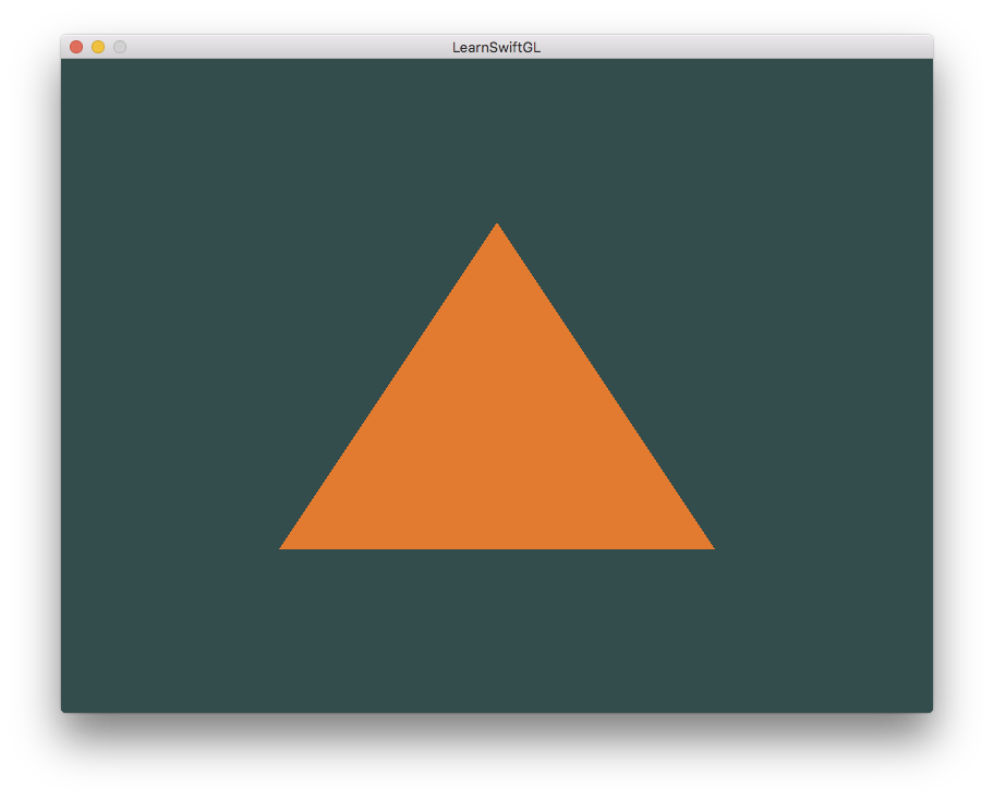
The source code for the complete program can be found here.
If your output does not look the same you probably did something wrong along the way so check the complete source code, see if you missed anything or ask below in the comments section.
Element Buffer Objects
There is one last thing we’d like to discuss when rendering vertices and that is element buffer objects abbreviated to EBO. To explain how element buffer objects work it’s best to give an example: suppose we want to draw a rectangle instead of a triangle. We can draw a rectangle using two triangles (OpenGL mainly works with triangles). This will generate the following set of vertices:
let vertices:[GLfloat] = [
    // First triangle
     0.5,  0.5,  // Top Right
     0.5, -0.5,  // Bottom Right
    -0.5,  0.5,  // Top Left
    // Second triangle
     0.5, -0.5,  // Bottom Right
    -0.5, -0.5,  // Bottom Left
    -0.5,  0.5   // Top Left
]
As you can see, there is some overlap on the vertices specified. We specify Bottom Right and Top Left twice! This is an overhead of 50% since the same rectangle could also be specified with only 4 vertices, instead of 6. This will only get worse as soon as we have more complex models that have over 1000s of triangles where there will be large chunks that overlap. What would be a better solution is to store only the unique vertices and then specify the order at which we want to draw these vertices in. In that case we would only have to store 4 vertices for the rectangle, and then just specify at which order we’d like to draw them. Wouldn’t it be great if OpenGL provided us with a feature like that?
Thankfully, element buffer objects work exactly like that. An EBO is a buffer, just like a vertex buffer object, that stores indices that OpenGL uses to decide what vertices to draw. This so called indexed drawing is exactly the solution to our problem. To get started we first have to specify the (unique) vertices and the indices to draw them as a rectangle:
let vertices:[GLfloat] = [
     0.5,  0.5, 0.0,  // Top Right
     0.5, -0.5, 0.0,  // Bottom Right
    -0.5, -0.5, 0.0,  // Bottom Left
    -0.5,  0.5, 0.0   // Top Left
]
let indices:[GLuint] = [  // Note that we start from 0!
    0, 1, 3,  // First Triangle
    1, 2, 3   // Second Triangle
]
You can see that, when using indices, we only need 4 vertices instead of 6. Next we need to create the element buffer object:
var EBO:GLuint = 0
glGenBuffers(n: 1, buffers: &EBO)
defer { glDeleteBuffers(1, &EBO) }
Similar to the VBO we bind the EBO and copy the indices into the buffer with glBufferData. Also, just like the VBO we want to place those calls between a bind and an unbind call, although this time we specify GL_ELEMENT_ARRAY_BUFFER as the buffer type.
glBindBuffer(target: GL_ELEMENT_ARRAY_BUFFER, buffer: EBO)
glBufferData(target: GL_ELEMENT_ARRAY_BUFFER,
    size: strideof(GLuint) * indices.count,
    data: indices, usage: GL_STATIC_DRAW)
Note that we’re now giving GL_ELEMENT_ARRAY_BUFFER as the buffer target. The last thing left to do is replace the glDrawArrays call with glDrawElements to indicate we want to render the triangles from an index buffer. When using glDrawElements we’re going to draw using indices provided in the element buffer object currently bound:
glBindBuffer(target: GL_ELEMENT_ARRAY_BUFFER, buffer: EBO)
glDrawElements(GL_TRIANGLES, 6, GL_UNSIGNED_INT, nil)
The first argument specifies the mode we want to draw in, similar to glDrawArrays. The second argument is the count or number of elements we’d like to draw. We specified 6 indices so we want to draw 6 vertices in total. The third argument is the type of the indices which is of type GL_UNSIGNED_INT. The last argument allows us to specify an offset in the EBO (or pass in an index array, but that is when you’re not using element buffer objects), but we’re just going to leave this at 0.
The glDrawElements function takes its indices from the EBO currently bound to the GL_ELEMENT_ARRAY_BUFFER target. This means we have to bind the corresponding EBO each time we want to render an object with indices which seems again a bit cumbersome. It just so happens that a vertex array object also keeps track of element buffer object bindings. The element buffer object currently bound while a VAO is bound, is stored as the VAO’s element buffer object. Binding to a VAO thus also automatically binds its EBO.
A VAO stores the glBindBuffer calls when the target is GL_ELEMENT_ARRAY_BUFFER. This also means it stores its unbind calls so make sure you don’t unbind the element array buffer before unbinding your VAO, otherwise it doesn’t have an EBO configured.
The resulting initialization and drawing code now looks something like this:
// ..:: Initialization code :: ..
// 1. Bind Vertex Array Object
glBindVertexArray(VAO)
    // 2. Copy our vertices array in a vertex buffer for OpenGL to use
    glBindBuffer(target: GL_ARRAY_BUFFER, buffer: VBO)
    glBufferData(target: GL_ARRAY_BUFFER,
        size: strideof(GLfloat) * vertices.count,
        data: vertices, usage: GL_STATIC_DRAW)
    // 3. Copy our index array in a element buffer for OpenGL to use
    glBindBuffer(target: GL_ELEMENT_ARRAY_BUFFER, buffer: EBO)
    glBufferData(target: GL_ELEMENT_ARRAY_BUFFER,
        size: strideof(GLuint) * indices.count,
        data: indices, usage: GL_STATIC_DRAW)
    // 4. Then set the vertex attributes pointers
    glVertexAttribPointer(index: 0, size: 3, type: GL_FLOAT,
        normalized: false, stride: GLsizei(strideof(GLfloat) * 3), pointer: nil)
    glEnableVertexAttribArray(0)
// 5. Unbind VAO (NOT the EBO)
glBindVertexArray(0)

[...]

// ..:: Drawing code (in Game loop) :: ..
glUseProgram(shaderProgram)
glBindVertexArray(VAO)
glDrawElements(GL_TRIANGLES, 6, GL_UNSIGNED_INT, nil)
glBindVertexArray(0)
Running the program should give an image as depicted below. The left image should look familiar and the right image is the rectangle drawn in wireframe mode. The wireframe rectangle shows that the rectangle indeed consists of two triangles.

Wireframe mode
To draw your triangles in wireframe mode, you can configure how OpenGL draws its primitives via glPolygonMode(GL_FRONT_AND_BACK, GL_LINE). The first argument says we want to apply it to the front and back of all triangles and the second line tells us to draw them as lines. Any subsequent drawing calls will render the triangles in wireframe mode until we set it back to its default using glPolygonMode(GL_FRONT_AND_BACK, GL_FILL).
If you have any errors, work your way backwards and see if you missed anything. Also, you can find the complete source code here.
If you managed to draw a triangle or a rectangle just like we did then congratulations, you managed to make it past one of the hardest parts of modern OpenGL: drawing your first triangle. This is a difficult part since there is a large chunk of knowledge required before being able to draw your first triangle. Thankfully, we now made it past that barrier and the upcoming tutorials will hopefully be much easier to understand.
Additional resources
- antongerdelan.net/hellotriangle: Anton Gerdelan’s take on rendering the first triangle.
- open.gl/drawing: Alexander Overvoorde’s take on rendering the first triangle.
- antongerdelan.net/vertexbuffers: some extra insights into vertex buffer objects.
Exercises
To really get a good grasp of the concepts discussed a few exercises were set up. It is advised to work through them before continuing to the next subject to make sure you get a good grasp of what’s going on.
- Try to draw 2 triangles next to each other using glDrawArrays by adding more vertices to your data.
- Now create the same 2 triangles using two different VAOs and VBOs for their data: solution.
- Create two shader programs where the second program uses a different fragment shader that outputs the color yellow; draw both triangles again where one outputs the color yellow.